Infiltration
A.J. Erickson, J.S. Gulliver, R.M. Hozalski, O. Mohseni, J.L. Nieber, B.N. Wilson, P.T. Weiss
Various stormwater treatment practices use infiltration as a primary or supportive process for stormwater treatment. When developing a water budget for a specific practice, it is important to consider infiltration and determine whether infiltration will represent a significant fraction of the total water outflow. For example, a dry pond may use sedimentation as the primary treatment process, but if the structure does not have an impermeable liner, it could also infiltrate a significant portion of the stormwater entering the pond. Neglecting infiltration may result in discrepancies between water inflow and water outflow in water budget analysis.
Infiltrometers and permeameters measure the infiltration rate at a specific location within a stormwater treatment practice. Infiltration rates typically are variable by orders of magnitude over space. Therefore, several measurements throughout an area are required to determine a representative infiltration rate if capacity testing is used to estimate the overall infiltration rate. Synthetic runoff testing and monitoring may also be used to estimate infiltration. The next section provides detailed information on infiltration measurement devices.
Infiltration Measurement Devices
Infiltration rate can be measured by two distinct methods in stormwater treatment practices: synthetic runoff testing and capacity testing. Synthetic runoff testing measures the rate at which water infiltrates into the entire practice, utilizing a depth measurement device. Capacity testing is the average of several infiltration measurements from points throughout the stormwater treatment practice, made from infiltrometers and permeameters.
Various devices are available for simple estimations of infiltration at a specific location within a stormwater treatment practice such as the single ring infiltrometer, double ring infiltrometer, Philip-Dunne permeameter, Guelph permeameter, and tension infiltrometer. Most infiltration measurement devices also require soil moisture to be measured, procedures for which can be found in Soil Science Society of America Book Series: 5, Methods of Soil Analysis, Part 1, “Physical and Mineralogical Methods” (Klute 1986). Infiltration can also be estimated by numerical methods such as the Horton and Green-Ampt models.
Single Ring Infiltrometer
Single-ring infiltrometers (figure 4.11), as described by Bedient and Huber (1992), are one tool used to measure infiltration. A 30-centimeter (11.81 inches) diameter, 20-centimeter (7.87 inches) tall ring is driven approximately 5 cm (1.97 inches) into the ground and filled with water (Klute 1986). By measuring the depth of water in the ring as a function of time, the rate at which water moves into the ground is determined when the infiltration rate becomes constant. The soil surrounding the ring may also be flooded to encourage vertical flow of water into the soil.
Double Ring Infiltrometer
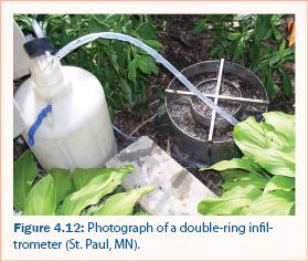
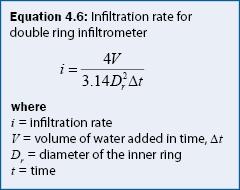
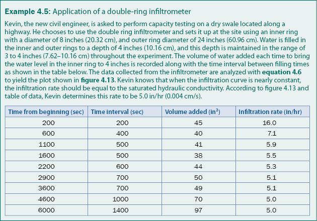
A double-ring infiltrometer (figure 4.12) is made of two concentric tubes, typically of thin metal or hard plastic, that are both continuously filled with water such that a constant water level is maintained as water infiltrates into the soil (A.S.T.M. 2005). The rate at which water is added to the center tube is measured and equation 4.6 is used to determine the infiltration rate from the field data.
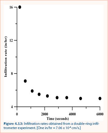
A typical plot of the infiltration rate versus time for a double-ring infiltrometer is shown in figure 4.13. After a certain period of time, the infiltration rate will become constant. When constant, the rate of infiltration is assumed to be equivalent to the saturated hydraulic conductivity. Steady state conditions may require about 20–30 minutes, but the duration of this experiment is dependent on the type and initial moisture content of the soil. An example of using equation 4.6 to measure the infiltration rate using a double ring infiltrometer is given in example 4.5.
Guelph Permeameter and tension infiltrometer
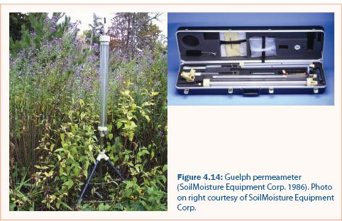
The Guelph permeameter (GP, figure 4.14) is another tool for measuring soil-water properties (Bagarello et al. 2004). The GP estimates field-saturated hydraulic conductivity, matrix flux potential, and soil sorptivity based on constant-head calculations (SoilMoisture Equipment Corp. 1986).
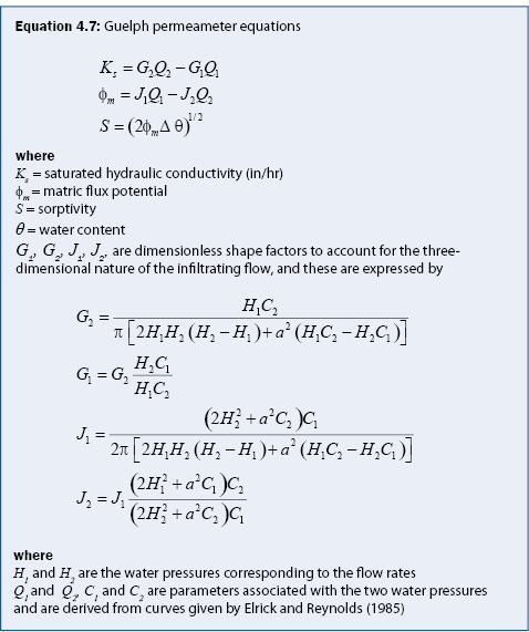
The Guelph permeameter (GP) is a constant-head well permeameter consisting of a mariotte reservoir that maintains a constant water level inside an augered hole that is typically 4 inches (10.16 centimeters) deep, cored into the unsaturated soil. This permeameter requires steady discharge from two different water levels (heads) in the augered hole. Steady-state discharges are measured at two different water pressure heads. Generally, the water pressure heads are a 2-inch (5.08 centimeter) head to give a discharge of Q1, and a 4-inch (10.16 centimeter) head for a discharge of Q2, as recommended by the manufacturer. The measured discharges are used with the change in volumetric water content (Δθ) to determine field-saturated hydraulic conductivity (Ks), matric flux potential (φm), and sorptivity (S). Equations for these parameters are given in equation 4.7. The parameters G1, G2, J1, J2, are dimensionless shape factors to account for the three-dimensional nature of the infiltrating flow and are determined based on the diameter of the auger hole and the values of the applied pressure heads. Expressions for these parameters are also given in equation 4.7.
A limitation of the GP is that it is applied to a borehole and not to the soil surface. Therefore, the effect of the top layer of the stormwater treatment practice surface is not reflected in the results. An alternative test to the conventional GP is a GP with a tension infiltrometer (TI) where the TI is auxiliary equipment available for the GP. For unsaturated soil conditions, a tension infiltrometer can be added to the Guelph permeameter setup (figure 4.14).
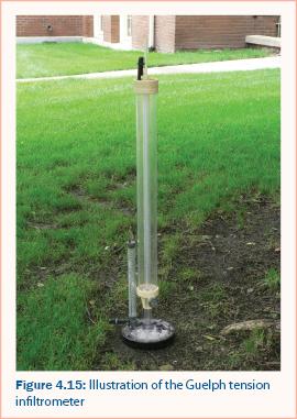
The tension infiltrometer consists of a porous disc (available in 4 inch or 8 inch (10.16–20.32 centimeter) diameter) connected to a Mariotte reservoir. An illustration of the tension infiltrometer is presented in figure 4.15. The procedures for using the method are described by Reynolds and Elrick (1991). In applying the method, the porous disc is placed in contact with the soil surface. This usually requires that vegetation and debris be removed from the surface and that the surface be flat. In many cases, it is also desirable to place a thin layer of fine sand onto the soil surface to provide good contact between the disc and the soil.
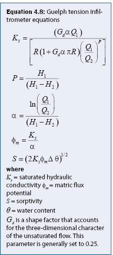
Once the disc is in place on the soil surface, the steady-state discharge for infiltration into the soil are measured for two applied water pressures, H1 and H2, where H1< H2. The TI can facilitate the measurement of unsaturated hydraulic conductivity for various applied tensions, but typically for stormwater treatment practices, only the saturated hydraulic conductivity value is desired. To estimate this value, the pressures need to be slightly negative (i.e., tension). It is recommended that successive pressures of –5 cm (1.97 inch) (H1) and –1 cm (.394 inch) (H2) be used. At each of these pressures the corresponding steady-state discharge (Q1 and Q2) is measured. The steady-state discharge and change in volumetric moisture content (Δθ) are used in equation 4.8 derived by Reynolds and Elrick (1991) to find the desired soil properties.
Philip-Dunne Permeameter
The Philip Dunne permeameter (Munoz-Carpena et al. 2002) estimates saturated hydraulic conductivity using falling-head kinetics and is made of a plastic or metal tube that is inserted between 5 and 15 centimeters (1.97–5.91 inches) into the ground. Munoz-Carpena, et al. (2002) utilized an electrical sensor to detect and record the moment when the tube became empty, but a Philip-Dunne permeameter does not require this feature.
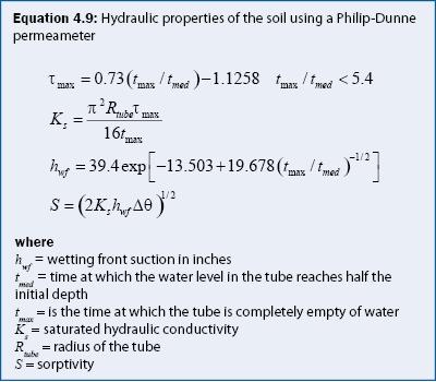
In the standard Philip-Dunne permeameter procedure, a tube is inserted into the bottom of an auger hole of the same radius. The initial moisture content of the soil is measured, the tube is filled with water, and the observer measures the time required for the water level in the tube to reach the halfway mark on the tube as well as the time required for the tube to empty completely. After the experiment, the final water content is measured. Generally, the porosity of the soil can be used as the final water content because the soil should be saturated in the vicinity of the auger hole. The radius of the tube, the two measured times, and the measured initial moisture content along with the final water content are used to estimate the hydraulic properties of the soil. The equations for performing this are given in equation 4.9.

Modified Philip-Dunne Infiltrometer
The Modified Philip Dunne (MPD) Infiltrometer is a new technique to measure the saturated hydraulic conductivity of surface soil. It is a falling head device and suitable for infiltration practices because it can be performed relatively quickly to capture the large spatial variability that commonly occurs with infiltration rates. It is suitable for assessment of required maintenance because accumulation of fine particle limits the infiltration rate in these practices. The MPD Infiltrometer is a fast, simple and inexpensive device. Using a spreadsheet program and the initial and final moisture content of the soil, the saturated hydraulic conductivity of the soil, K, can be determined. Since K values typically have a large variability (Warrick and Nielson 1980) it is useful to have a number of samples to estimate the mean value of the practice. Typically the MPD Infiltrometer has been used at up to 10 locations at a time, allowing for up to 20 measurements per day. The MPD, however, can only measure the hydraulic conductivity of the top 50 cm of media and does not detect if there is a confining layer underneath.
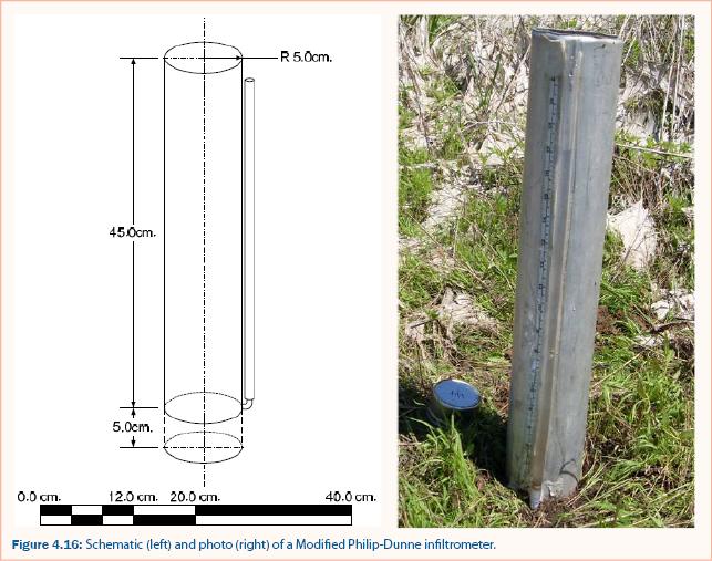
The MPD Infiltrometer, shown in figure 4.16, is an open ended 50cm long cylinder constructed out of 2mm thickness, 10cm diameter and is made of aluminum pipe. The bottom edge of the cylinder is beveled from the outside to ease the process of inserting the device 5 cm into the soil surface. A hole at 5cm from the bottom is connected to a piezometer tube. Alongside the piezometer tube a metric measuring tape is adhered. Inside the cylinder a fine meshed screen is adhered to prevent media from entering the piezometric tube.
Recommendations
Infiltration rates can vary spatially by orders of magnitude depending on many factors such as soil texture, plant root structure, porosity, soil moisture, etc. It is thus essential to take many measurements of saturated hydraulic conductivity on an infiltration practice to determine an overall mean value that has sufficient accuracy. Infiltration measurements using the Modified Philip-Dunne Infiltrometer are recommended to determine the saturated hydraulic conductivity in the upper 30 cm because the measurements are relatively quick and can be accomplished with minimal water. The Modified Philip-Dunne Infiltrometer is recommended to determine saturated hydraulic conductivity below 30 cm from the surface, again because of ease of application.
Continue to Evaporation and Evapotranspiration.